The Googlher
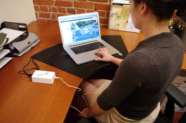
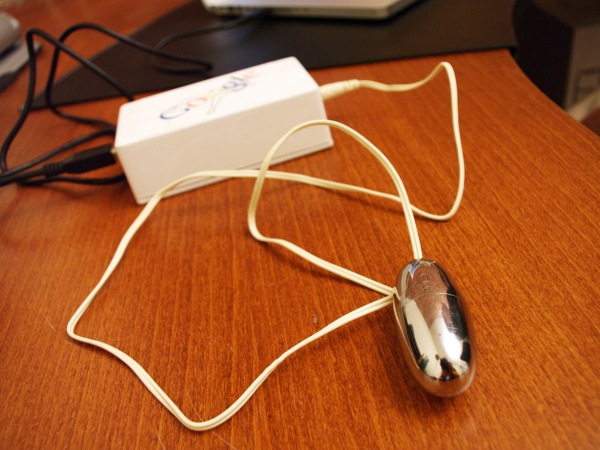
Follows are directions to make your own Google-responsive vibrator. Build one and let Google touch you where it counts.
Materials:
(x1) The Googlher Firefox addon (download source)
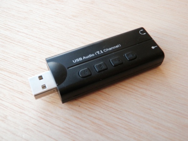
(x1) USB Audio Dongle (with headphone jack)
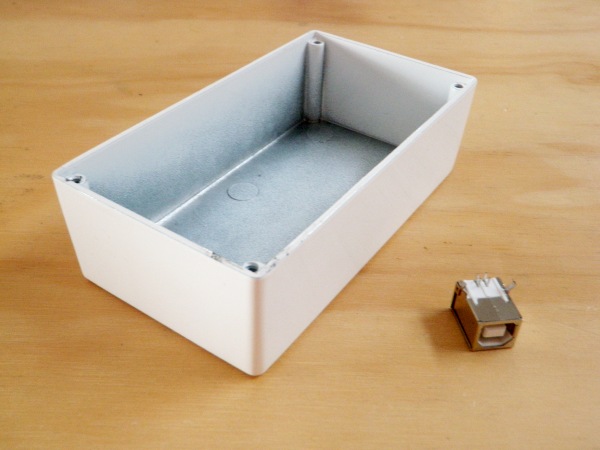
(x1) Hammond 125-B white powder coated case
(x1) Silver Bullet Vibrator
(x1) Female USB-B jack
(x1) Female USB-A jack (I got mine from a Mac G4 keyboard that has them built in for the mice)
(x2) PCBs
(x1) HT9170 DTMF decoder
(x1) CD4021 shift register
(x1) Arduino (with ATMEGA328 DIP chip)
(x1) 16MHz crystal
(x1) 3.579545MHz crystal
(x4) 22pf capacitors (x3) 0.1uF capacitor
(x1) 100uF capacitor (x1) 10uF capacitor
(x2) 100K resistors (x1) 300K resistor
(x4) 10K resistors (x1) 1K resistor
(x1) 1N4001 diode (x1) IRF510A MOSFET
(x1) 1″ shrink tubing
(x1) 12″ square of 1/8″ acrylic
(x1) 6″ square of 3/8″ acrylic
(x4) nuts and bolts
(x1) Printable transparent sticker sheet
(x1) misc. tape and glue
(x1) soldering setup
(x1) tools and junk
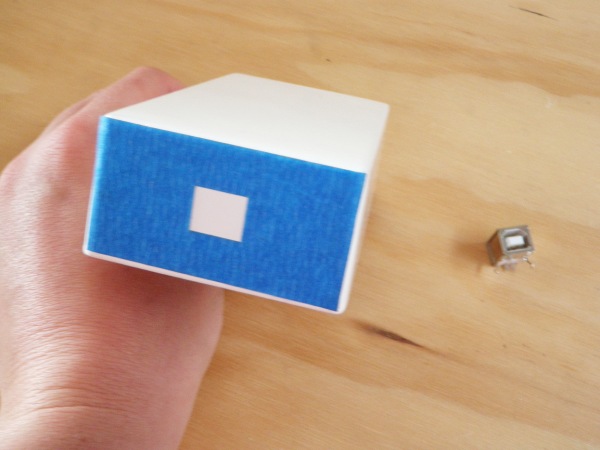
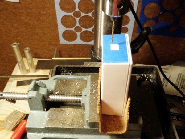
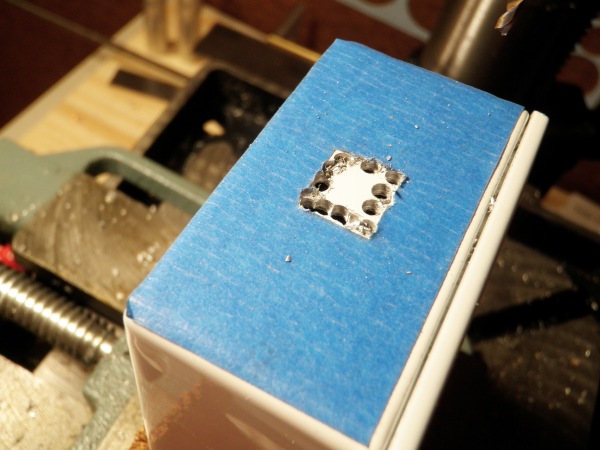
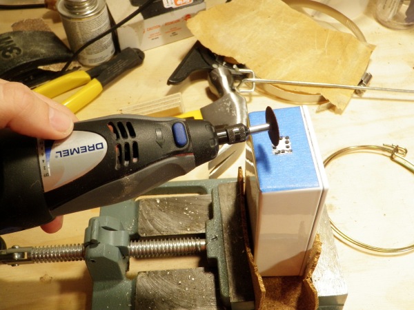
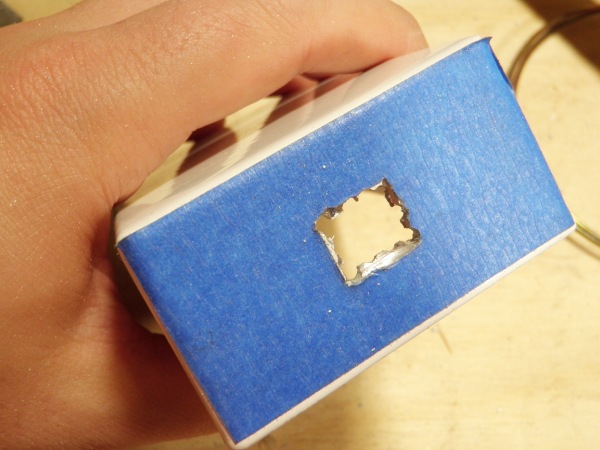
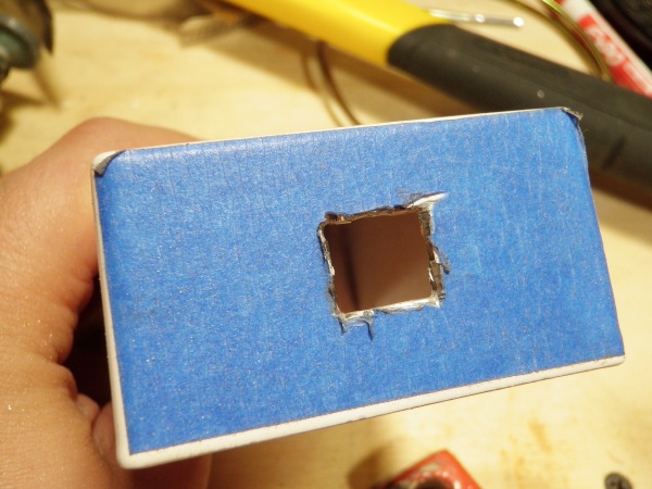
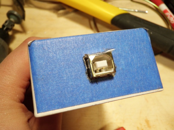
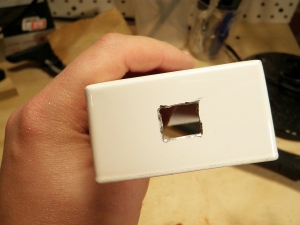
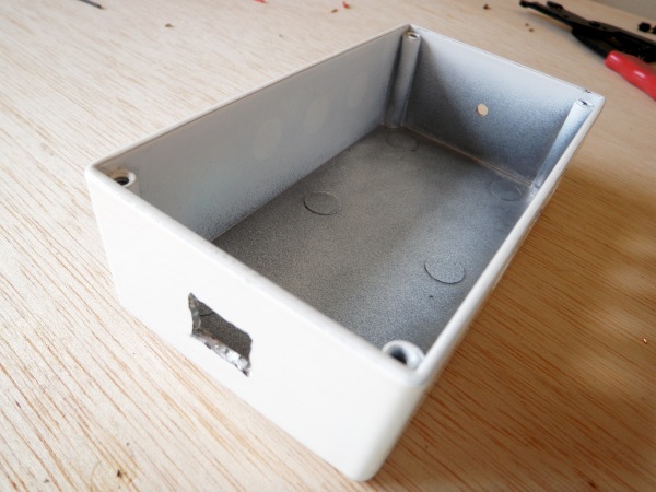
The first thing you need to do is to cut a square hole in the side of your case in which to put the USB jack. I cut a template out of painters tape using a laser cutter and this file: If you don’t have a laser cutter, just print it out the file, cut it out and affix it to the case. Drill around the inside perimeter of the hole and then cut it out with a Dremel. Once you have done this, carefully widen the hole until it’s nice and square. Your USB jack should now fit inside. Note: The hole in the template is now slightly bigger than the jack. I have widened it to account for the heat shrink tubing that we later use to insulate the jack from the case.
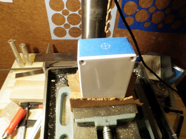
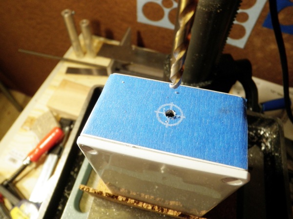
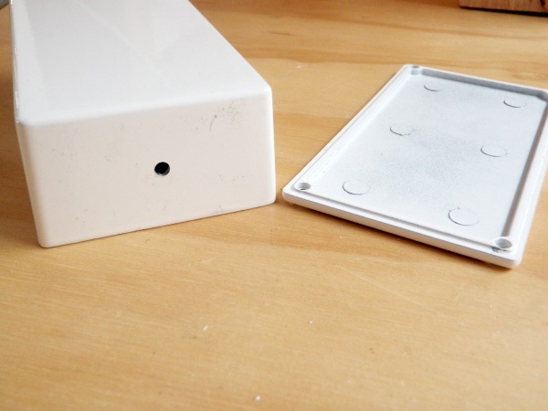
After you have made a nice square hole in one side, it is time to make a tiny round hole in the other. Use this file as your guide: Affix your guide to the case and drill a 1/4″ hole (or appropriate for your jack… always measure).
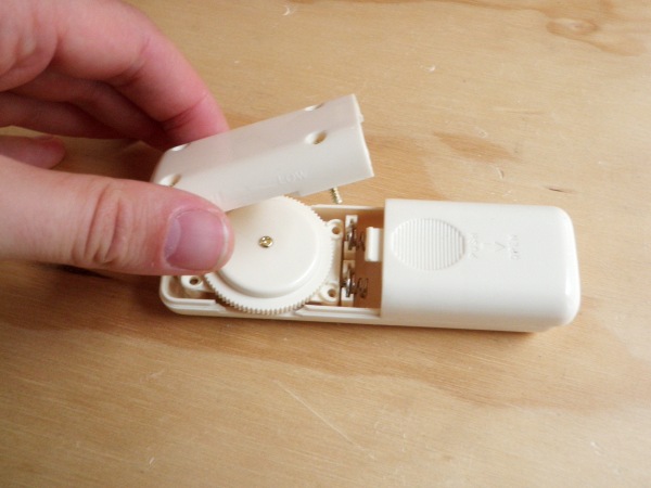
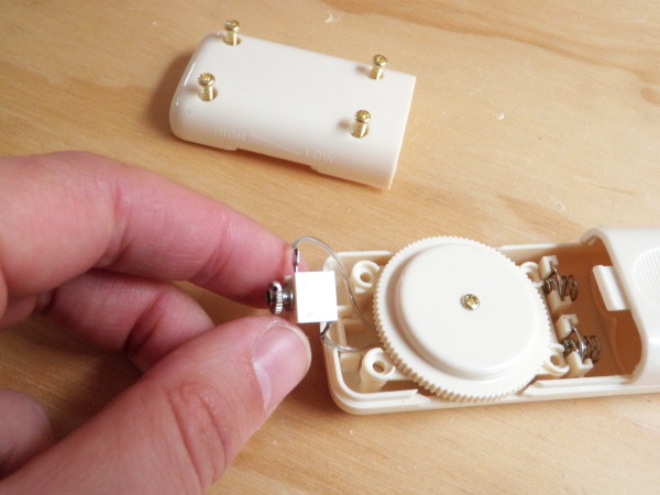
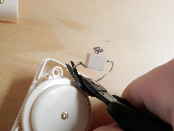
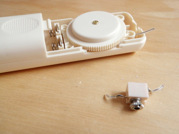
Open up the vibrator controller and remove the 3/32″ (2.5mm) jack.
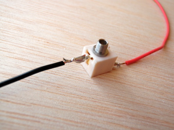
Attach new longer wires to each terminal of the jack.
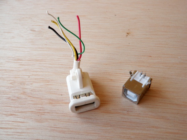
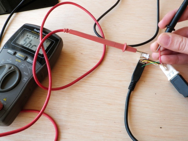
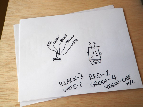
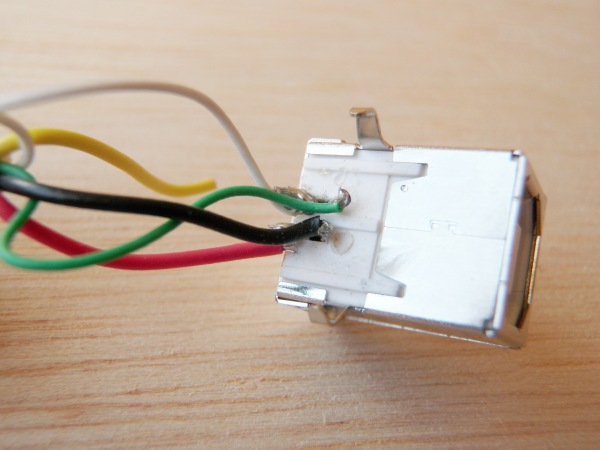
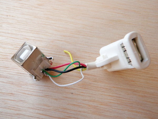
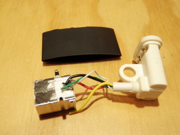
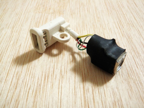
Wire together the USB-B jack and the female USB-A jack that was pulled from the Mac keyboard. To figure out which wire goes to which terminal, plug in a USB cable between the two and use a multimeter to test for continuity (or just look at my cheat sheet below).
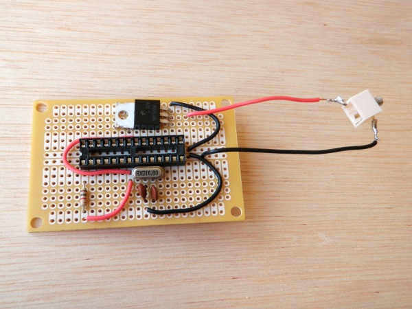
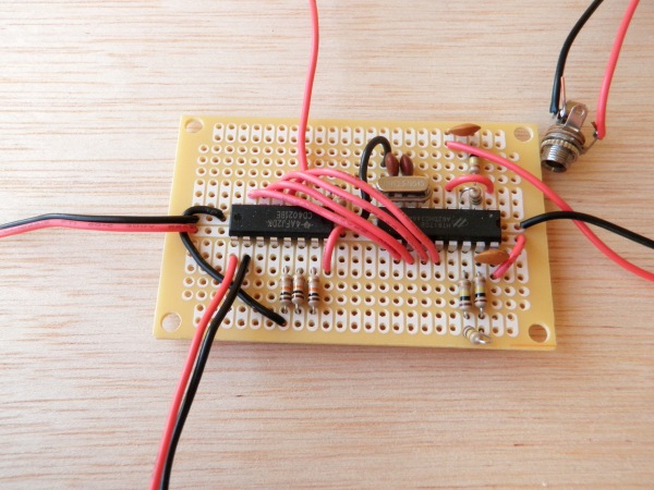
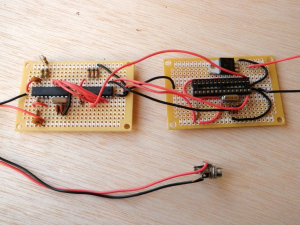
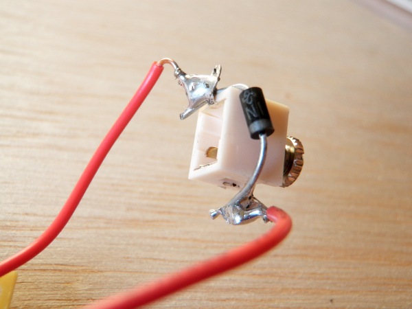
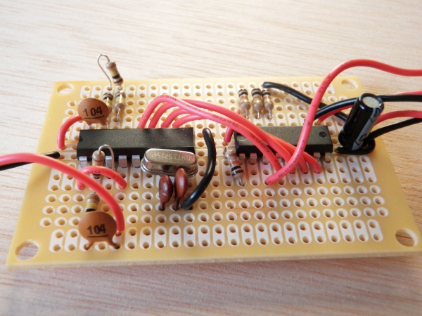
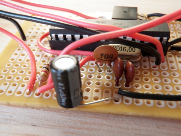
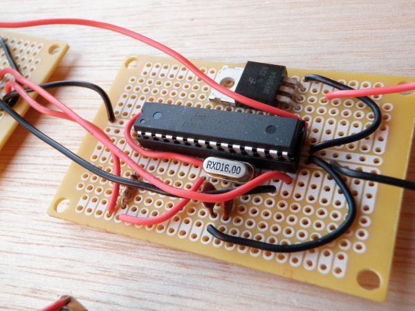
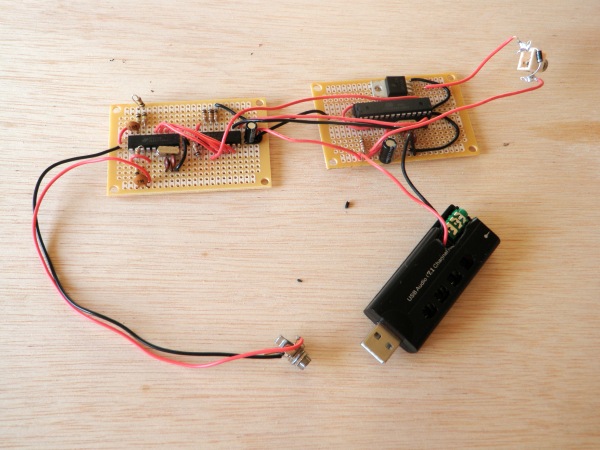
It is circuit building time. First, let us understand what is happening. A DTMF tone from the Firefox addon is sent via the audio port of the USB dongle into a HT9170 DTMF decoder. The decoder chip sets 4 consecutive pins to either high (5v) or low (0v) depending on the tone it detects. These 4 pins are connected to the inputs of a CD4021 shift register, which in turn converts them into a 4-bit number between 0 and 15. This number is sent to the ATMEGA328 chip, which is programmed using the Arduino development board. The ATMEGA328 finally takes the number it receives and vibrates the motor accordingly. The circuit is pretty straight forward, but there are a few things to note. First of all, on account of the power demands of the motor, the circuit needs a couple filter capacitors to function reliably. I put a 47uF capacitor where the power source enters the board. I put 0.1uF capacitor between positive and ground as close to the ATMEGA328 as possible. I also put a 10uF cap near the power source to shift register. This seemed to do the trick for me. If your chip stops working reliably for you, my advice is to keep adding more filter caps until it does (very scienterific like). Also, the power and audio are wired directly to the USB dongle. For the sake of keeping troubleshooting easy, I don’t wire these in until later. The audio jack is left wired in for as long as possible. I am powering the board at this point with alligator clip connector wires. I have also added a 1N4001 diode to the 3/32″ (2.5mm) jack to minimize the effects of voltage spikes from the motor. Lastly, make sure you solder everything to the circuit boards with as low of a profile as possible. For everything else, just look at the schematic. It is relatively straight-forward.
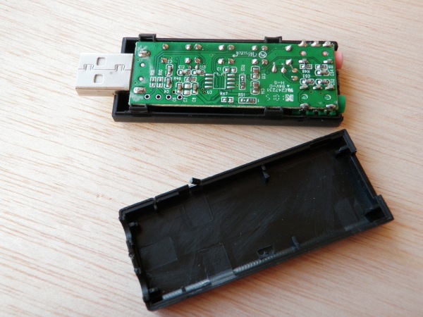
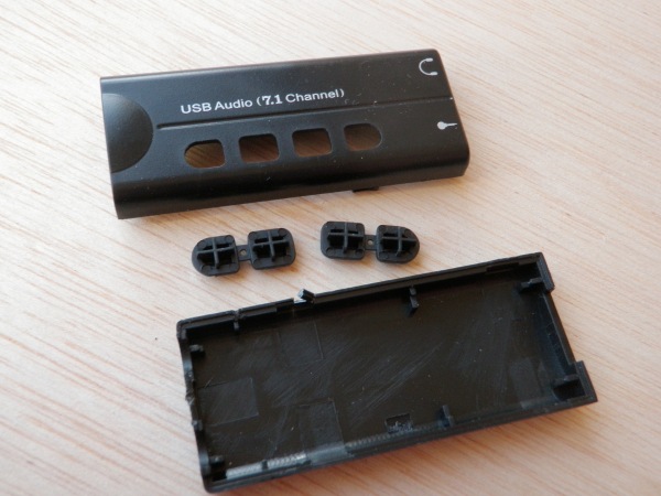
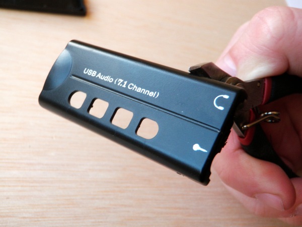
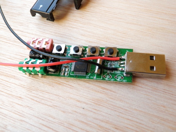
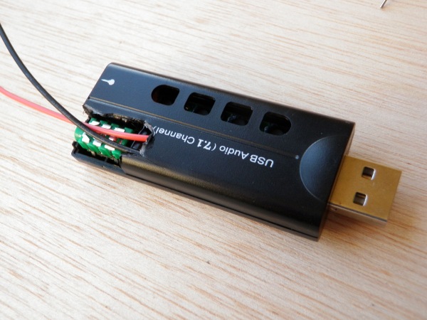
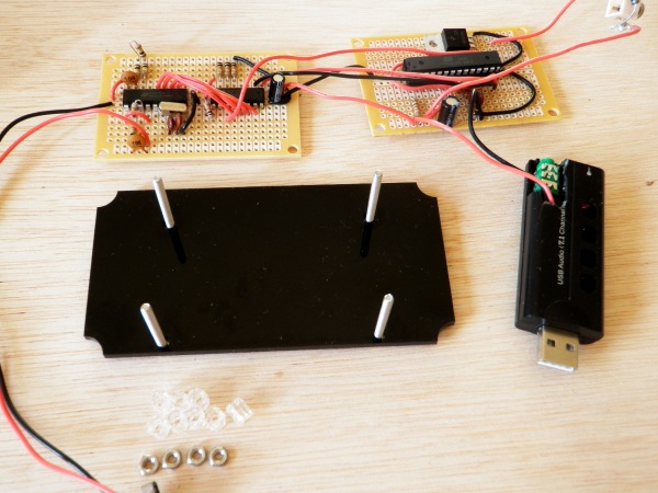
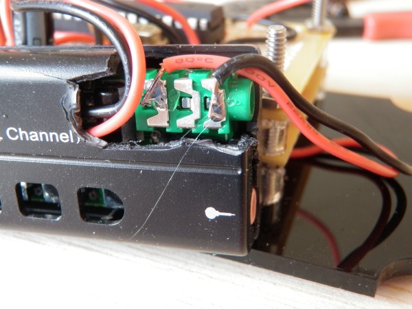
Open up your USB dongle. Attach a red and black wire to the USB jack as pictured. Remove any buttons from the casing that may interfere with normal operation. Break the case in such a way that the audio output jack is exposed and you can pass the power wires through. Once the modifications are made, close the case back up.
Program the Arduino with the following code:
Googlher Arduino Code
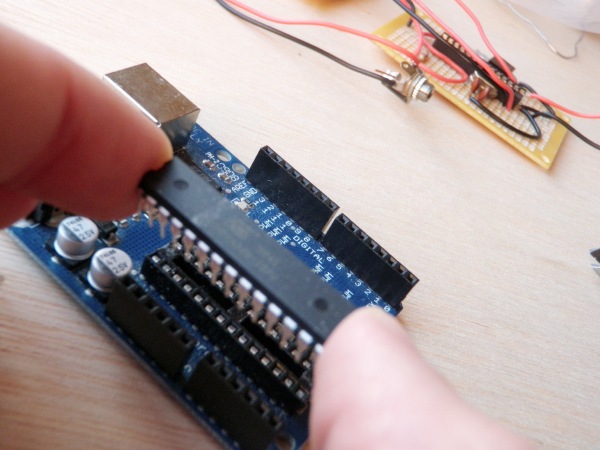
The code is basically built on top of Carlyn Maw’s shiftin code, with a whole bunch of case statements added on top. It is not the most elegant of Arduino programs, but it gets the job done. When the Arduino is programmed, transfer the ATMEGA168 to the socket on the circuit board.
Wire the power from the USB dongle to the circuit board as close to the 47uF filter capacitor as possible.
Laser cut the following file out of 1/8″ acrylic:
Bracket
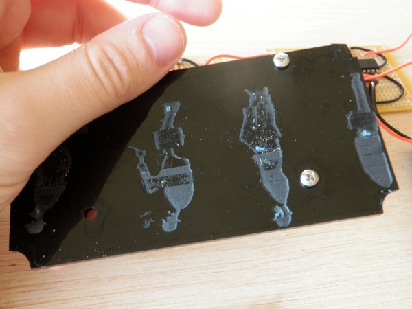
This is the mounting bracket. Any old acrylic is fine. I cut mine out of scrap acrylic with a botched etching of the Ministry of Funny Walks on the back. Then,
laser cut the following file out of 3/8″ acrylic:
Spacers
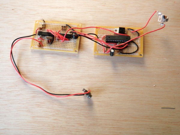
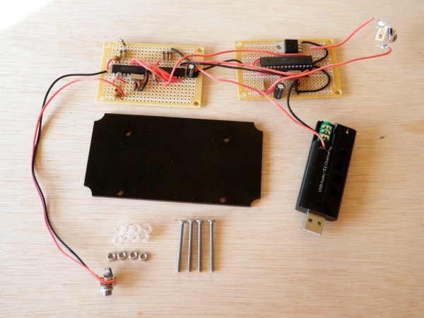
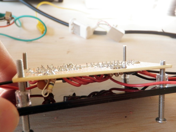
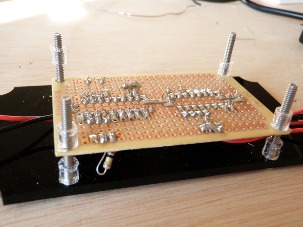
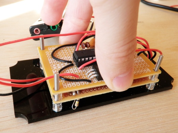
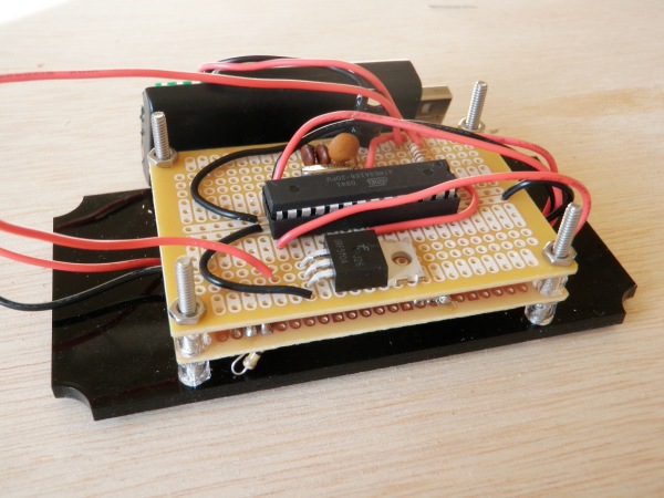
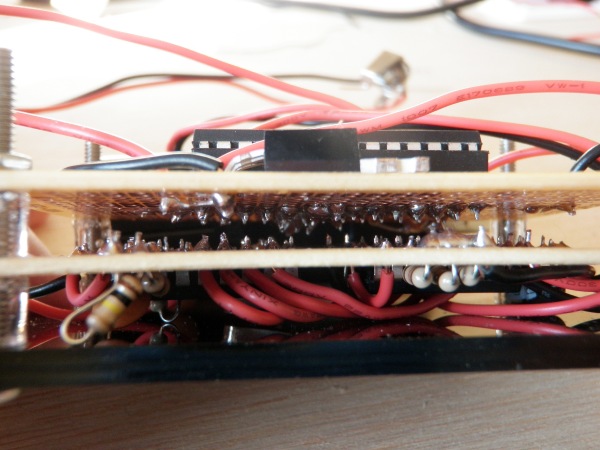
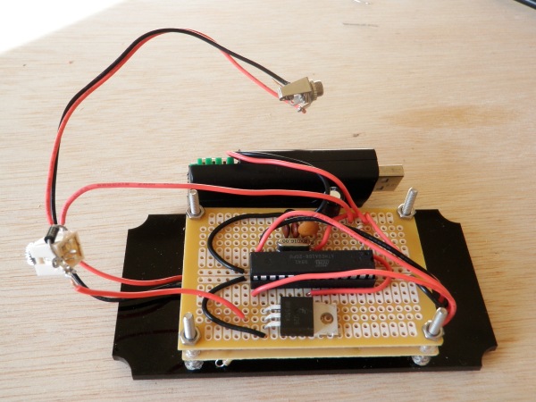
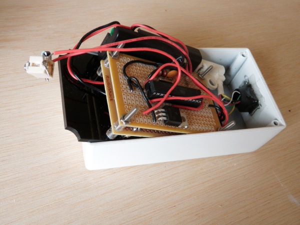
If you don’t have a laser cutter, you can use a service like ponoko.com or you can print out the files and just cut them out the old-fashioned way. Fasten the circuit boards to the bracket using your nuts, bolts and spacers. Make certain that none of the connections between the two boards accidentally touch each other. If you are confused, just look at these pictures.
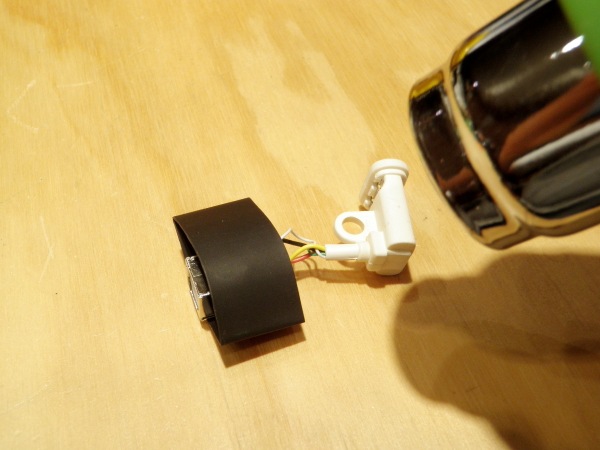
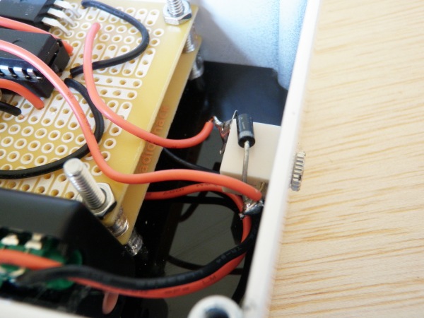
It turns out that when you insert a positively powered jack (the motor jack) and a negatively powered jack (the USB jack) into a metal case, it shorts the power and makes your computer’s USB jack really unhappy. Therefor, it is essential that one of these jacks be insulated. I felt like I had more wiggle room with the USB jack, so I insulated it with heat shrink tubing. For the job I used 1″ diameter heat shrink, but would probably have been better off with 3/4″ diameter tubing.
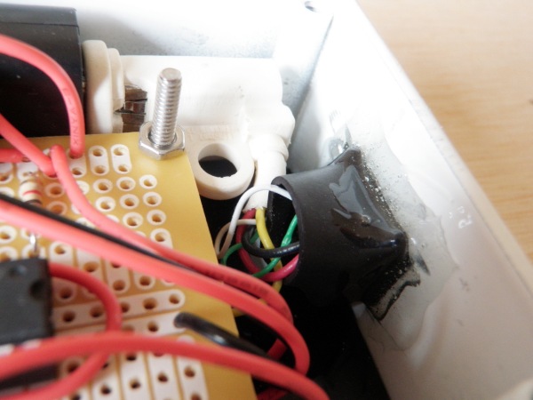
When you are certain that it is working, trim away the audio jack from the circuit board and solder the two audio wires to the USB dongle as pictured.
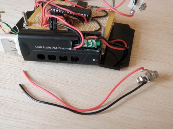
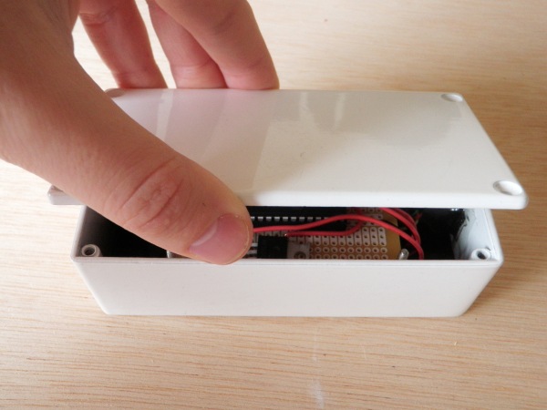
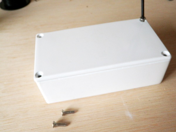
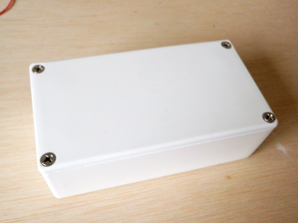
Epoxy the USB jack into case. (Shhhhh…. I also touched up the outside of the case around the USB jack with white enamel model paint.) Insert the circuit bracket into the body of the case. Plug in the USB Dongle. Fasten the 3/32″ jack. Put the lid on the case and fasten it shut with the screws.
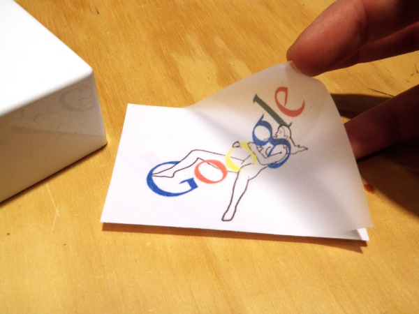
Download the following file:
Googlher
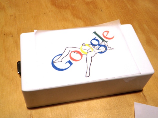
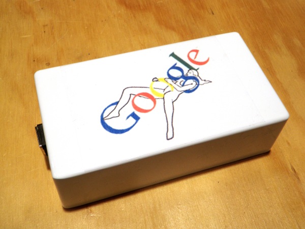
Print it on transparent sticker paper. Cut it to size and stick it to your case.
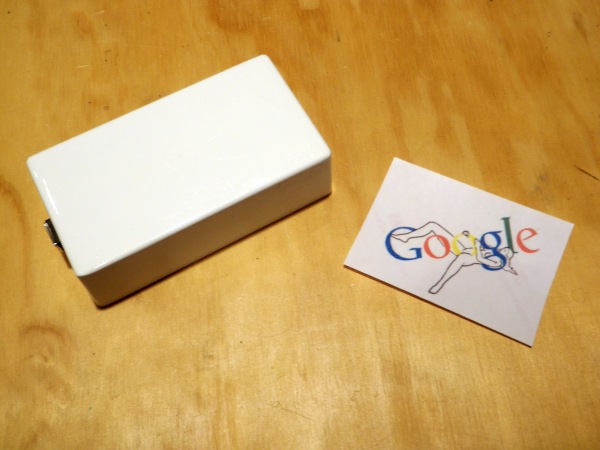
Download and install The Googlher Firefox addon if you haven’t done so already. Plug it in and enjoy!
Note: If you are hearing annoying beeps instead of feeling wonderful vibrations, then you need to configure your computer to output through the USB dongle instead of the built in speakers.
The expressions published in this site are all in the public domain. You may enjoy, use, modify, snipe about and republish all F.A.T. media and technologies as you see fit.


